SURGICAL VISION / TECHNOLOGY

Surgical technology.
Clearly explained.

Understand the science behind the image, the working space and the instrument. Know what to look for before choosing a surgical system.

EXPLORE THE TECHNOLOGY
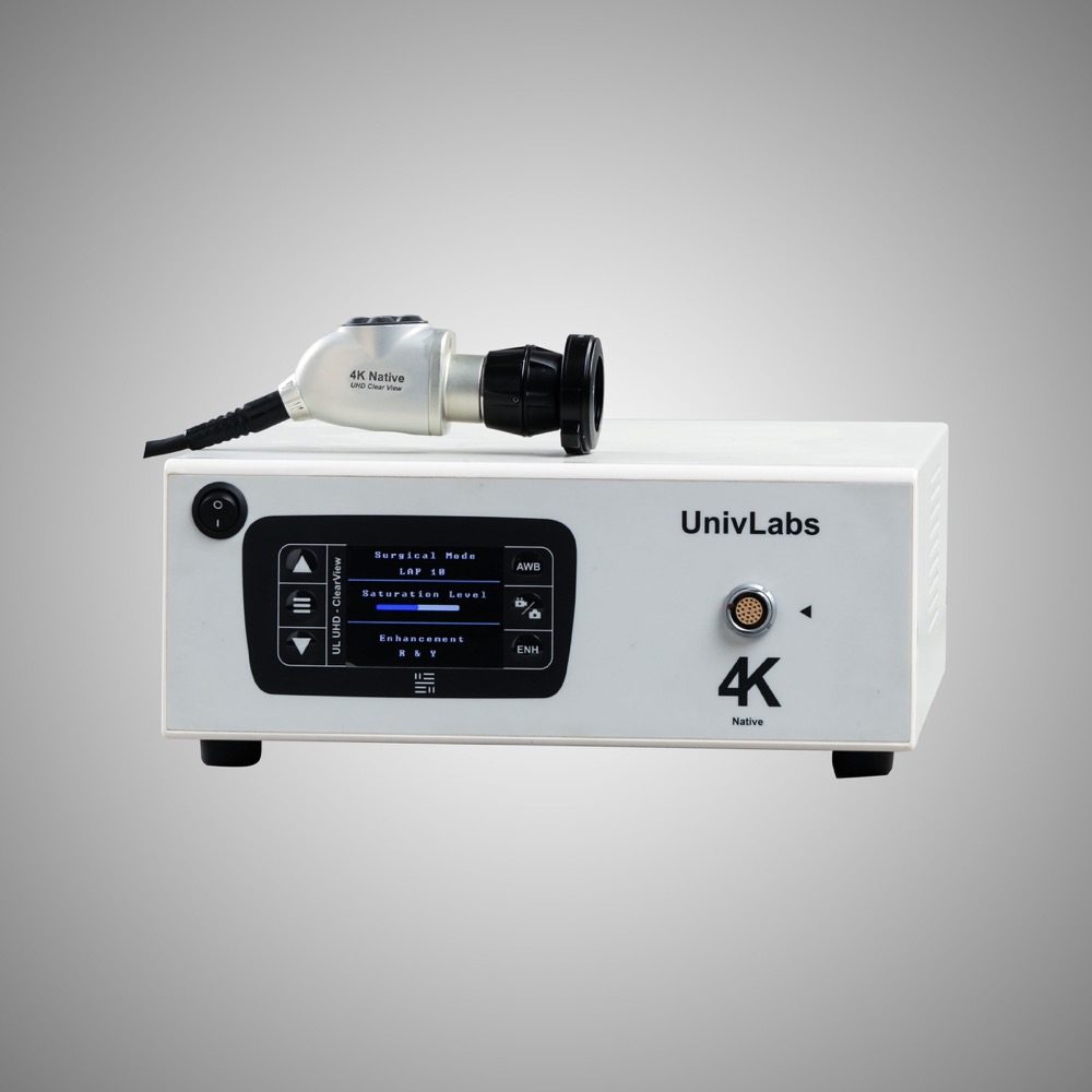
UnivLabs Non-ICG Camera
Non-ICG Camera1 / 10

01 / OPTICAL ENGINEERING

Optical technology & endoscopes

Two light paths. One surgical view.

A clear surgical image starts with the scope—not only the monitor.

Illumination
Light travels towards tissue
Image relay
Reflected light returns to the camera
Viewing angle
Direction of view ≠ field of view
SCIENCE, DIAGRAMS & FAQs
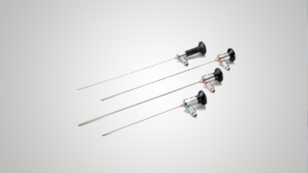
Rigid endoscopes with different viewing configurations
ENDOSCOPES

02 / CAMERA & SIGNAL CHAIN

Four-chip ICG camera system

Sensor count is only the beginning.

Understand sensor design, image processing and fluorescence compatibility.

4 chips
Number of image sensors
4K
Image resolution, not sensor count
NIR
A separate spectral requirement
SCIENCE, DIAGRAMS & FAQs
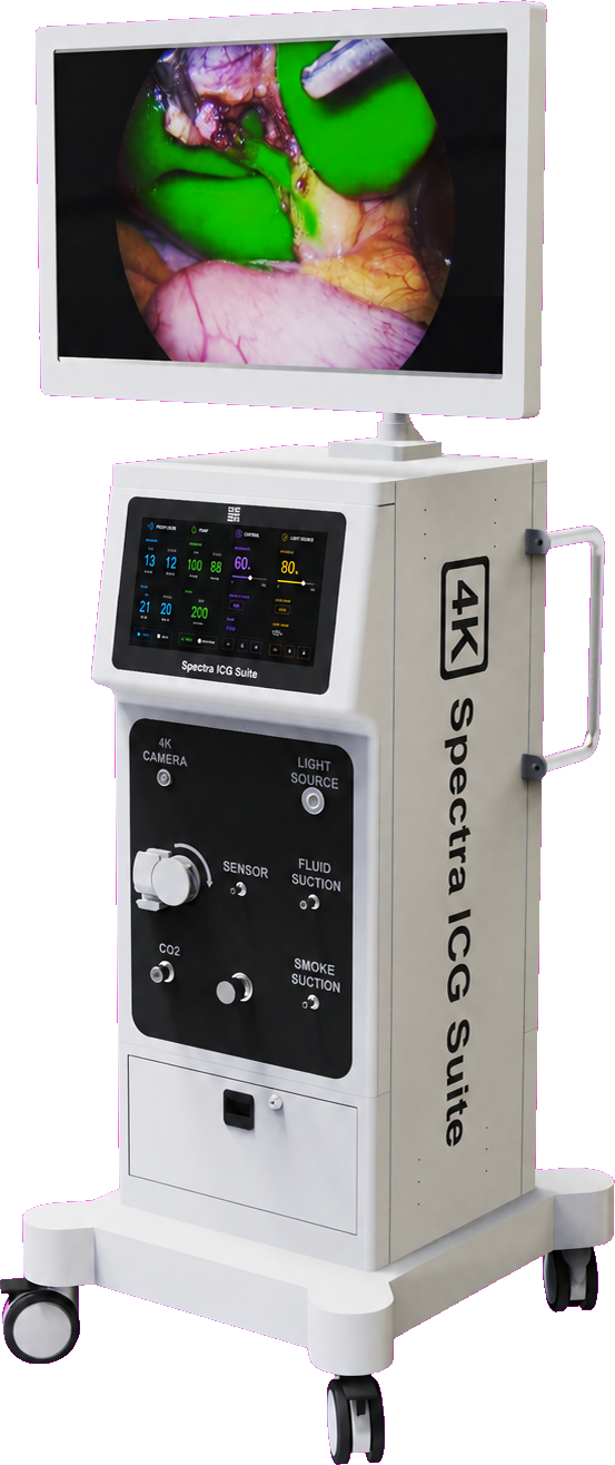
Spectra surgical suite including its camera system
SPECTRA SURGICAL VISION SUITE

03 / MULTIMODAL VISUALISATION

Colour, ICG & fluorescence

See anatomy. Then add another signal.

Different views answer different questions.

White light
Anatomical colour context
NIR view
Detected fluorescence signal
Overlay
Signal placed over the colour view
SCIENCE, DIAGRAMS & FAQs
Example fluorescence overlay on a surgical image
FLUORESCENCE OVERLAY · EXAMPLE

04 / SPECTRAL COMPATIBILITY

ICG light source & wavelengths

Excite one band. Detect another.

Excitation and detection are two different parts of the optical system.

805 nm
ICG absorption peak*
830 nm
ICG emission peak*
Matched optics
Source + cable + scope + detector
SCIENCE, DIAGRAMS & FAQs
Two sources. One light path.IR LEDWhite LEDCollection lensLensDichroiccombinerFocus lensLight guideIR is invisible; orange represents its path.
WHITE LIGHT + NEAR-INFRARED
Optical principle · actual design may vary. Lenses collect and focus light; the dichroic optic combines the spectral bands. Optics reference.

*805 nm and 830 nm are protein-bound ICG reference peaks. These are not LED output specifications.

05 / THE SCIENCE OF FLUORESCENCE

How fluorescence works

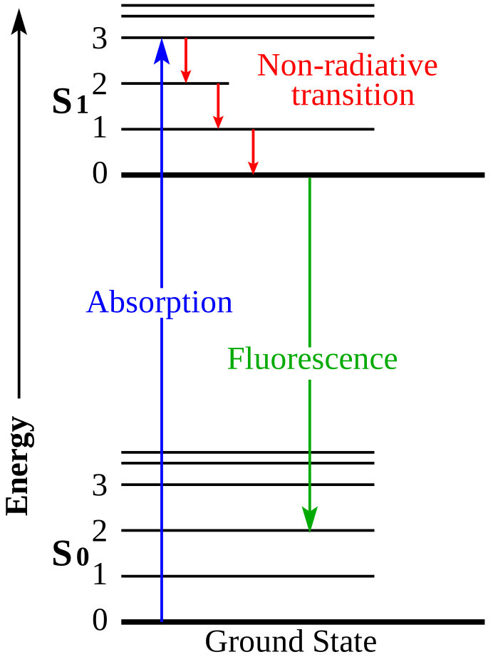
Absorb energy. Emit a new signal.

Make an otherwise invisible optical signal visible on screen.

Excitation
A photon supplies energy
Relaxation
Some energy is lost without light
Emission
A lower-energy photon is emitted
SCIENCE, DIAGRAMS & FAQs
Jablonski energy diagram showing absorption, non-radiative relaxation and fluorescence emission
Energy levels, not anatomy. Blue: absorption. Red: non-radiative relaxation. Green: fluorescence. Original by Jacobkhed; vectorisation by Д.Ильин. Source · CC0 1.0.

NIR / ICG

A signal beyond visible light.

Near-infrared describes a wavelength range. ICG is a fluorescent agent that can be excited and detected within that range. Depending on the authorised application, it can support visualisation of perfusion or anatomical structures.

  1. NIR excitation
  2. ICG fluorescence
  3. Filtered camera
  4. Display overlay

Protein-bound ICG has reference absorption and emission peaks near 805 and 830 nm. These are not universal camera or LED specifications.

IC-GREEN prescribing information ↗

BLUE-LIGHT FLUORESCENCE

Visible excitation. A different signal.

In blue-light cystoscopy, hexaminolevulinate supports the formation of fluorescent porphyrins in tissue. With suitable blue-light illumination and filters, fluorescence appears red against the blue background.

  1. Blue excitation
  2. Porphyrin fluorescence
  3. Filtered view
  4. White-light review

This is used alongside—not instead of—white-light examination. False signals and missed lesions remain possible. Other blue-light applications require their own agent and system assessment.

CYSVIEW mechanism and precautions ↗

CYTALUX® / PAFOLACIANINE

Targeted molecular fluorescence.

CYTALUX is a folate-receptor-targeted optical imaging agent, not a light colour or camera mode. A compatible NIR system detects its fluorescence during specified surgical applications.

  1. Targeted agent
  2. NIR excitation
  3. Compatible detector
  4. Surgeon interpretation

Its US label covers adjunctive identification of malignant ovarian lesions and malignant or non-malignant pulmonary lesions in adults with known or suspected lung cancer. Fluorescence alone does not establish malignancy.

CYTALUX prescribing information ↗

These are different agent–illumination–detector combinations, not interchangeable features. Spectra’s ICG capability does not establish support for blue-light agents or CYTALUX. Confirm the exact device, agent, intended use and local approvals. Fluorescence supplements clinical assessment; it does not replace it.

06 / PRESSURE & FLOW CONTROL

How an insufflator works

Maintain working space—not just flow.

Controlled gas delivery creates and maintains the laparoscopic working space.

Pressure
Measured in mmHg
Flow
Delivered volume per minute
Feedback
Regulation as conditions change
SCIENCE, DIAGRAMS & FAQs
Gas pathway & feedbackCO₂ supplyControllerGas deliveryWorking spacePressure feedback*Tubing, filters and ports affect delivery.
Working principle · simplified diagram. *Sensing and estimation depend on the system design.

07 / FLUID MANAGEMENT

Surgical fluid pumps

The displayed pressure needs context.

Manage irrigation and visualisation with the right system for the procedure.

Inflow
Fluid supplied to the field
Outflow
Fluid and debris removed
Site pressure
Depends on measurement method
SCIENCE, DIAGRAMS & FAQs
Fluid pathway & feedbackFluid supplyPumpInflow regulationWorking spacePressure feedback*Outflow and suction also affect site conditions.
Working principle · simplified diagram. *Sensing and estimation depend on the system design.

08 / RADIOFREQUENCY ENERGY

Electrosurgery & electrocautery

Understand the complete current path.

Know which energy pathway the instrument uses.

Monopolar
Separate patient return electrode
Bipolar
Two electrodes on the instrument
Electrocautery
A heated tip—not the same circuit
SCIENCE, DIAGRAMS & FAQs
Two electrical circuitsGeneratorActive electrodeTissueMonopolar: separate return electrodeGeneratorElectrode A → tissue → electrode BBipolar: the local circuit is at the instrument
Working principle · simplified diagram.

09 / MECHANICAL ENERGY

Ultrasonic / Harmonic technology

Electrical input. A vibrating blade.

Mechanical vibration provides another way to cut and coagulate tissue.

Transducer
Converts electrical energy
Waveguide
Transfers mechanical vibration
Blade
Creates the tissue effect
SCIENCE, DIAGRAMS & FAQs
Electrical to mechanical energyGeneratorElectrical inputTransducerPiezoelectricBladeMechanical motionMechanical vibration is not heat-free.
Working principle · simplified diagram.